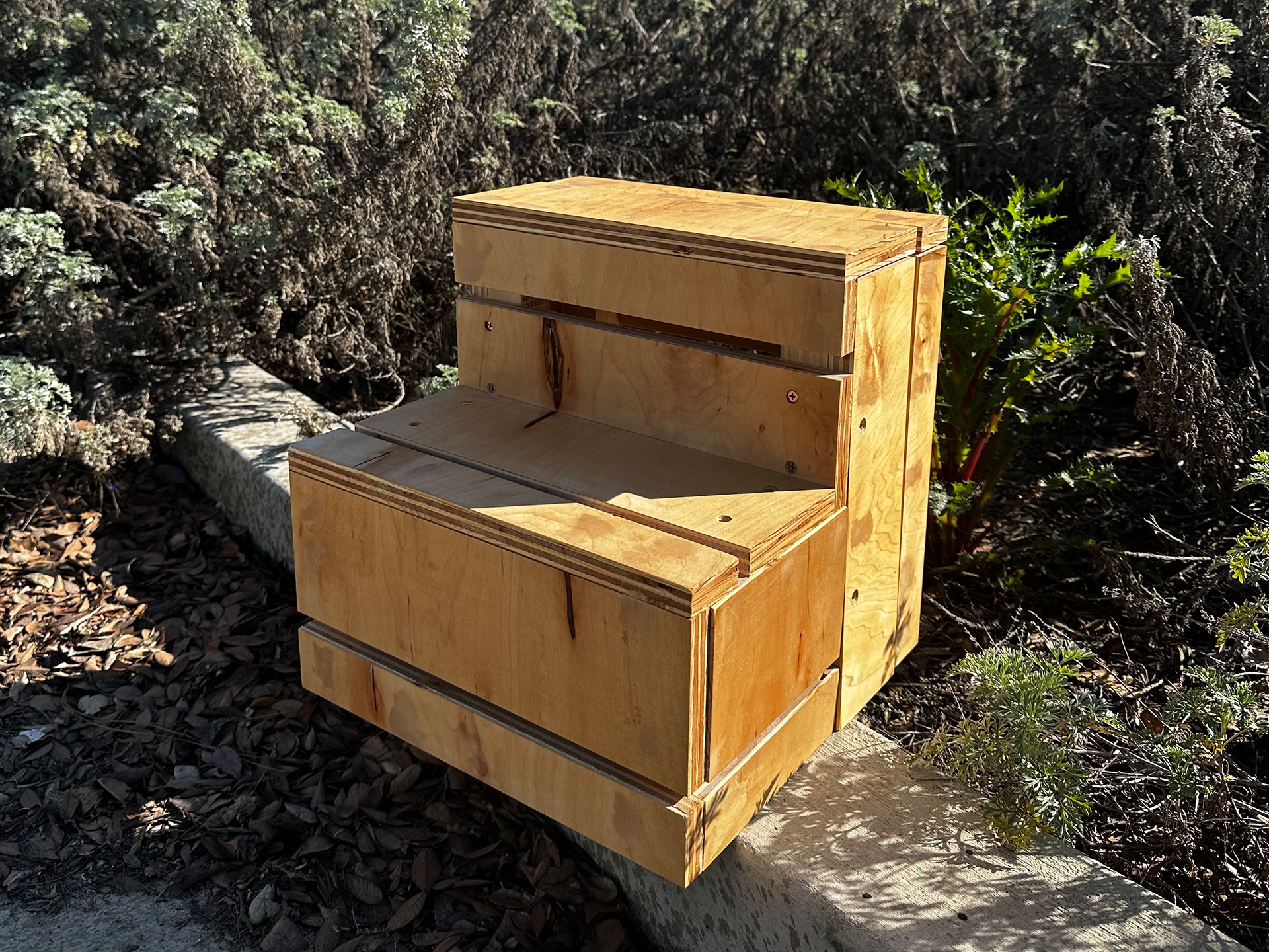
FINAL FURNITURE PROTOTYPE (Above): Final prototype of the modular step stool, photographed outside the Design Department Makerspace. The Social Step Stool project explores the boundaries between individual design and collective functionality.
Social Step Stool: A Modular Furniture
Year: 2026
Project Type: Furniture Design + Detailing
Institution: University of California, Davis
PROJECT SCOPE
Tasked with creating a step stool of precise dimensions (14” x 14” x 14”) using limited, standardized materials, each designer was encouraged to infuse their own creativity within strict guidelines. While each stool is a fully functional piece of furniture on its own, the true purpose lies in how multiple identical stools interact in a shared environment. When assembled, 24 of these modular stools become versatile building blocks—capable of stacking, rotating, and connecting to form larger social furniture configurations. This transforms a simple utilitarian object into a dynamic installation promoting social engagement and collaboration. The project emphasizes careful material efficiency, precise craftsmanship, and innovative joinery techniques. It also explores the relationship between individual design decisions and collective outcomes, asking: How can a single object maintain its identity while contributing to a greater whole?
STEP STOOL REQUIREMENTS
The step stool consists of two steps, each with a 7-inch rise and a 7-inch run, with plywood surfaces required on every step, rise, and run. Each step face must also cover at least 50% of three additional sides with plywood in some form.
MATERIALS PROVIDED
(Qty. 1) 24” x 48” x 3/4” plywood sheet
(Qty. 2) 2” x 4” x 96” limber (3” x 1.5” x 96” actual dimensions)
(Qty. 2) 2” x 4” x 96” limber (3” x 1.5” x 96” actual dimensions)
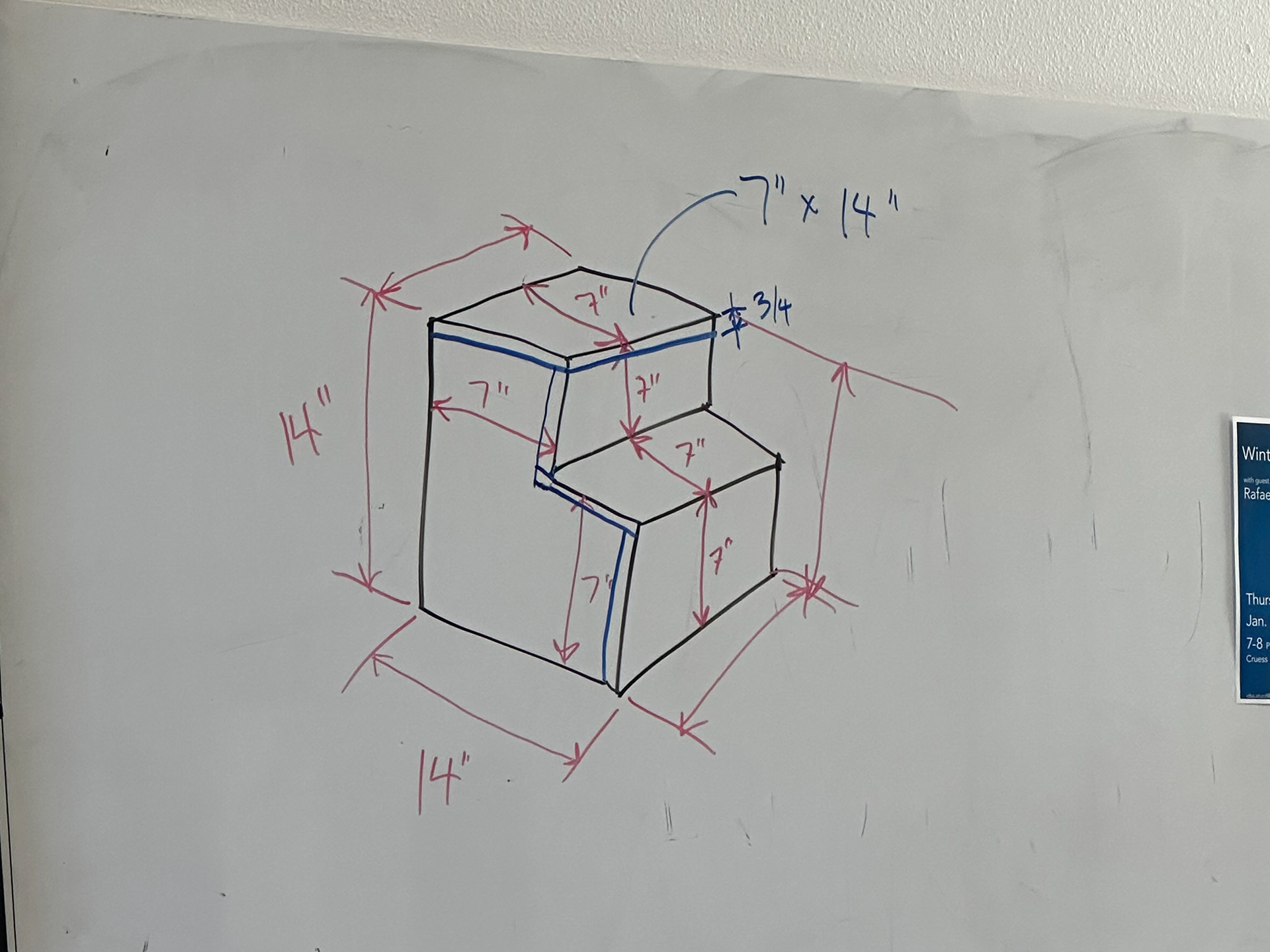
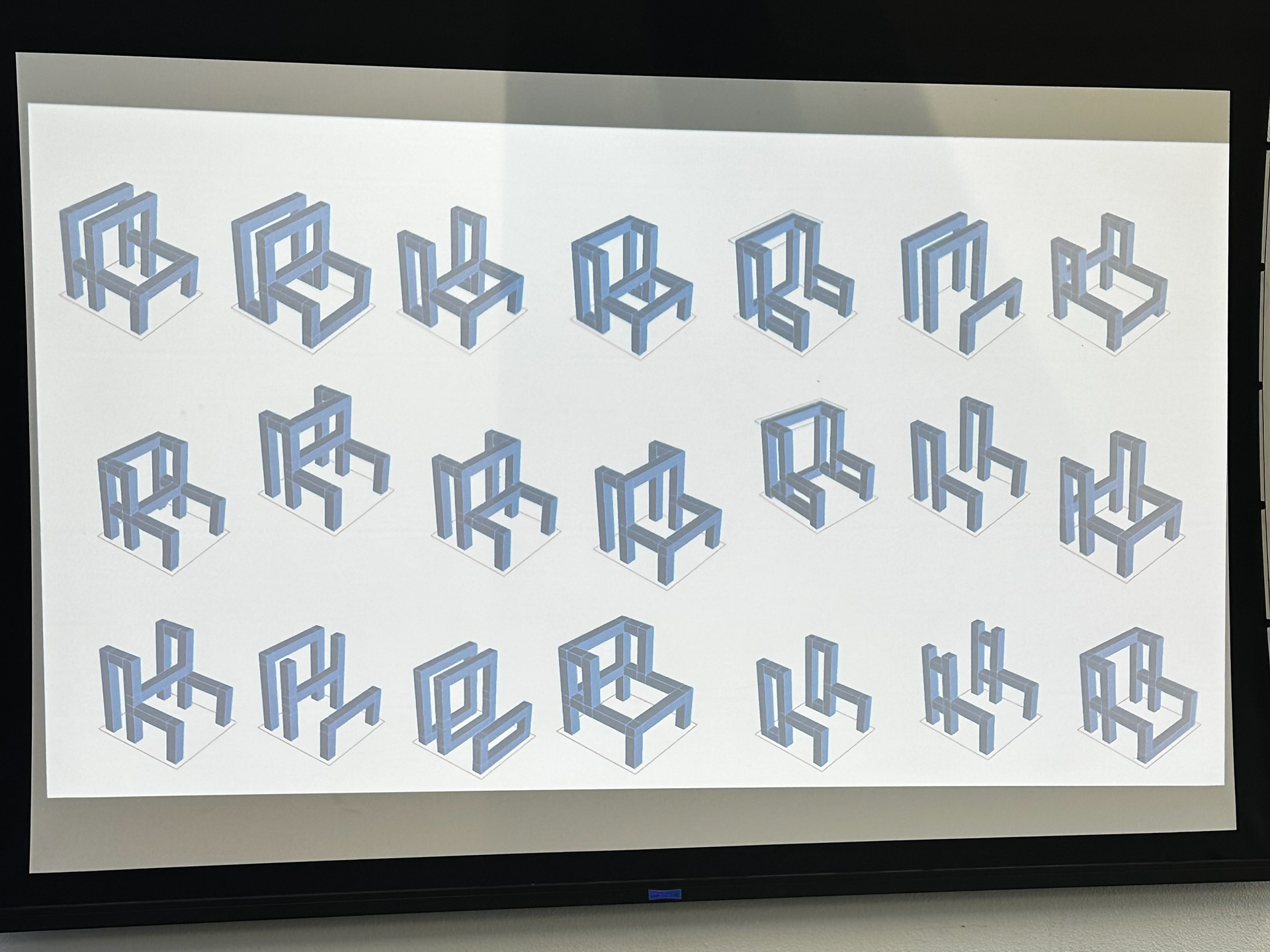
PREPARATION PROCESS (Above): Illustrates the measurement requirements for the 14"x14"x14" step stool, including two steps with a 7" rise and 7" run (Left). Illustrates possible framing configurations for constructing the step stool (Right).
FRAME WORK PLAN
The work plan began by determining the dimensions of each framing component based on the required 14” × 14” × 14” overall dimensions of the step stool and the two 2” × 4” × 96” lumber pieces provided. The framing was divided into five main components, labeled A–E, each measuring 1 ½” × 1 ½” in section:
A: 1 ½” × 1 ½” × 13 ¼” (4x); B: 1 ½” × 1 ½” × 2 ½” (2x); C: 1 ½” × 1 ½” × 9 ½” (3x); D: 1 ½” × 1 ½” × 7” (2x); E: 1 ½” × 1 ½” × 5 ½” (2x).
After establishing the individual component dimensions, a cut plan was developed to determine how each piece could be efficiently laid out across the two 96” lumber boards. The total required length of the framing components was calculated before cutting to minimize waste and preserve additional material in case of an inaccurate cut or measurement error. The components were strategically grouped onto the available lumber so that the longer pieces were cut first, followed by the shorter pieces, while accounting for the material removed by each saw cut.
FABRICATION PROCESS
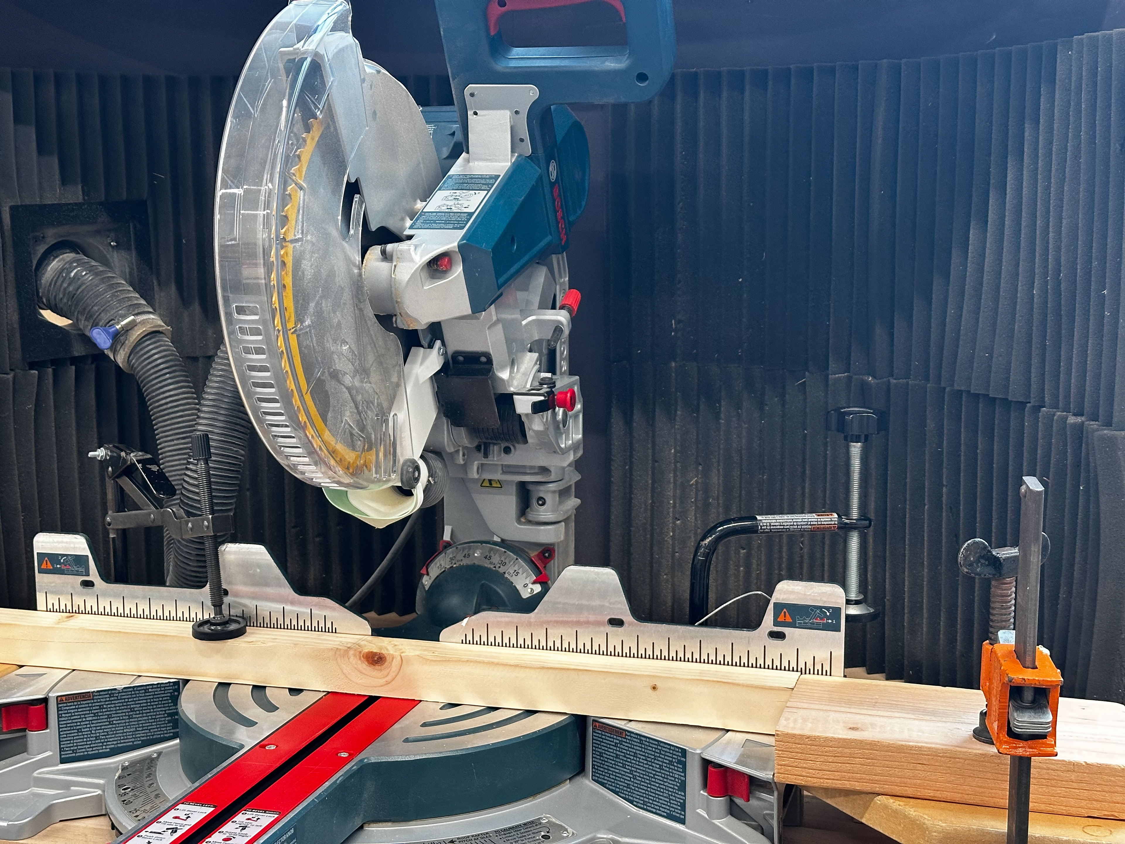
Using the cut plan as a guide, each component was measured, marked, and cut with a miter saw. Rather than cutting every piece at once, measurements were checked, and cuts were made progressively, using completed pieces to verify dimensions as the frame developed. This process helped maintain accuracy while allowing adjustments to be made before using additional material. The remaining lumber was also tracked throughout the process, ensuring that sufficient material was preserved as a buffer for potential errors or replacement pieces. Overall, the work plan served as both a cut sheet and fabrication strategy, connecting the dimensional requirements of the step stool to an efficient use of the available lumber.
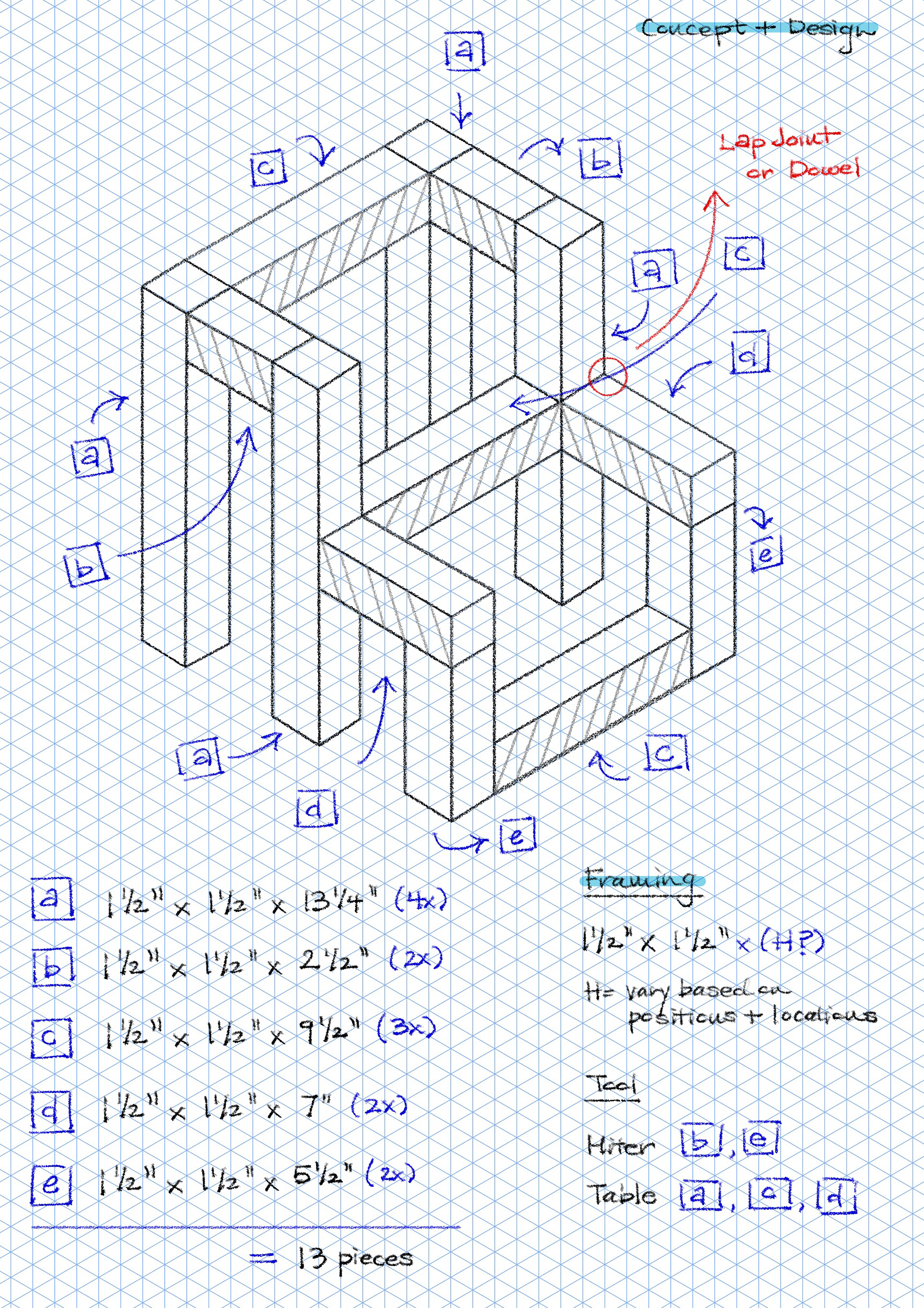
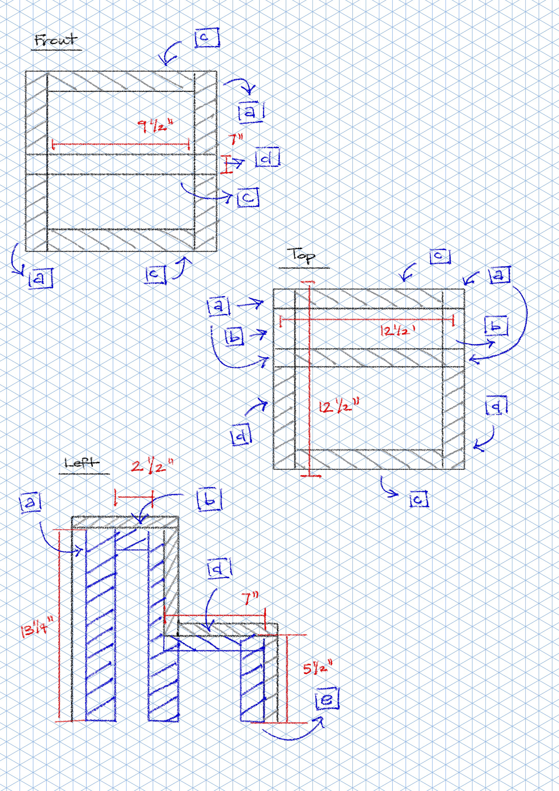
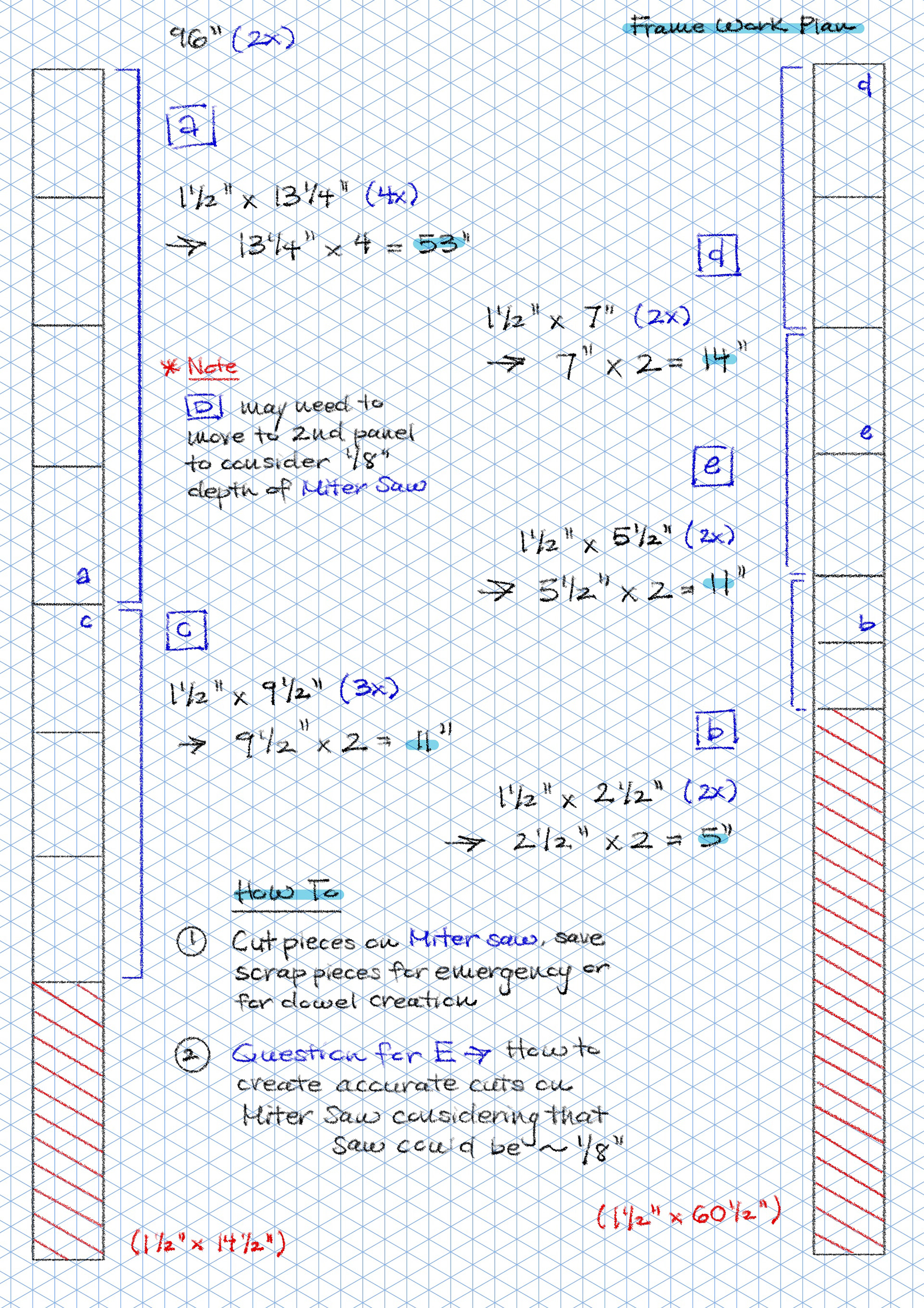
FRAMING WORK PLAN (Above): Framing study identifying five primary components, labeled A–E, and their corresponding dimensions and quantities. The drawing establishes how the individual lumber pieces work together to form the modular step stool frame while accounting for the 1½” × 1½” finished framing dimensions (Left). Orthographic dimensions of the front, top, and left-side views are used to verify the dimensions and placement of each framing component (Middle). A lumber cut plan was developed to efficiently organize the required A–E components across the two 2” × 4” × 96” lumber boards. The layout accounts for each piece’s dimensions, quantity, and saw kerf while reserving leftover material as a buffer for potential cutting or measurement errors (Right).
SKIN (PANELS) WORK PLAN
The skin panel work plan began by determining how the available 24” × 48” × 3/4” plywood sheet could be divided into the seven required panel components. Each panel was assigned a specific width and height based on the dimensions of the structural frame and the overall 14” × 14” × 14” step stool. The cut layout was organized to maximize the use of the plywood sheet while minimizing material waste. The panels were divided into seven components:
01: 2” × 14” × 3/4” (3x); 02: 4 1/2” × 14” × 3/4” (3x); 03: 3 3/4” × 14” × 3/4” (1x); 04: 2” × 13 1/4” × 3/4” (2x); 05: 3 3/4” × 13 1/4” × 3/4” (1x); 06: 4 1/2” × 7” × 3/4” (2x); 07: 2” × 7” × 3/4” (2x);
The plywood cut plan was developed by first breaking the 24” × 48” sheet into long strips based on the required width of each panel component. These strips were cut accurately on the table saw, allowing multiple pieces with the same width to be produced efficiently. Once the strips were established, each individual panel was measured and cut to its required height using the miter saw. This two-stage process helped maintain consistent dimensions across the repeated components while making efficient use of the limited plywood sheet.
FABRICATION PROCESS
After all seven panel components were cut, the pieces were fitted onto the structural frame of the step stool and secured using a combination of drilled screws and a nail gun. The panels were positioned carefully to align with the framing and create the finished exterior skin of the stool. Any remaining plywood scraps were retained for potential future use, while the completed panel edges were cleaned and prepared for the final finish.


SKIN (PANELS) WORK PLAN (Above): Dimensional study identifying the seven plywood panel components required to skin the step stool (Left). Cut layout for the 24” × 48” × 3/4” plywood sheet, organized to efficiently produce all seven panel components. The layout establishes the sequence for cutting the plywood into strips on the table saw before accurately sizing each panel on the miter saw. The plan also identifies the cutting sequence, use of scrap material, and preparation of the panels for assembly (Right).
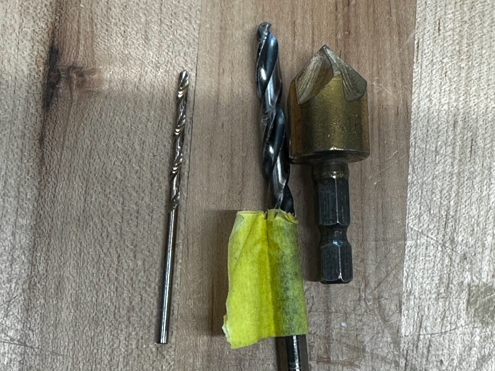
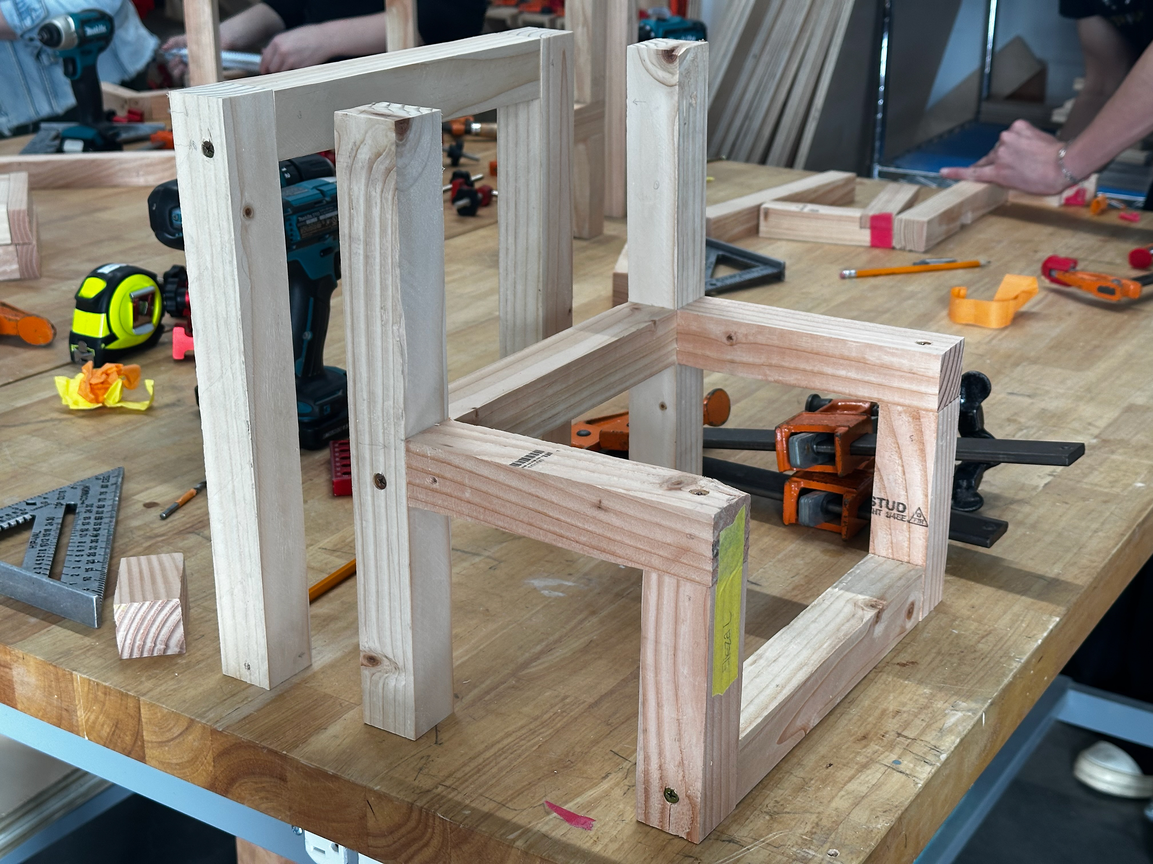
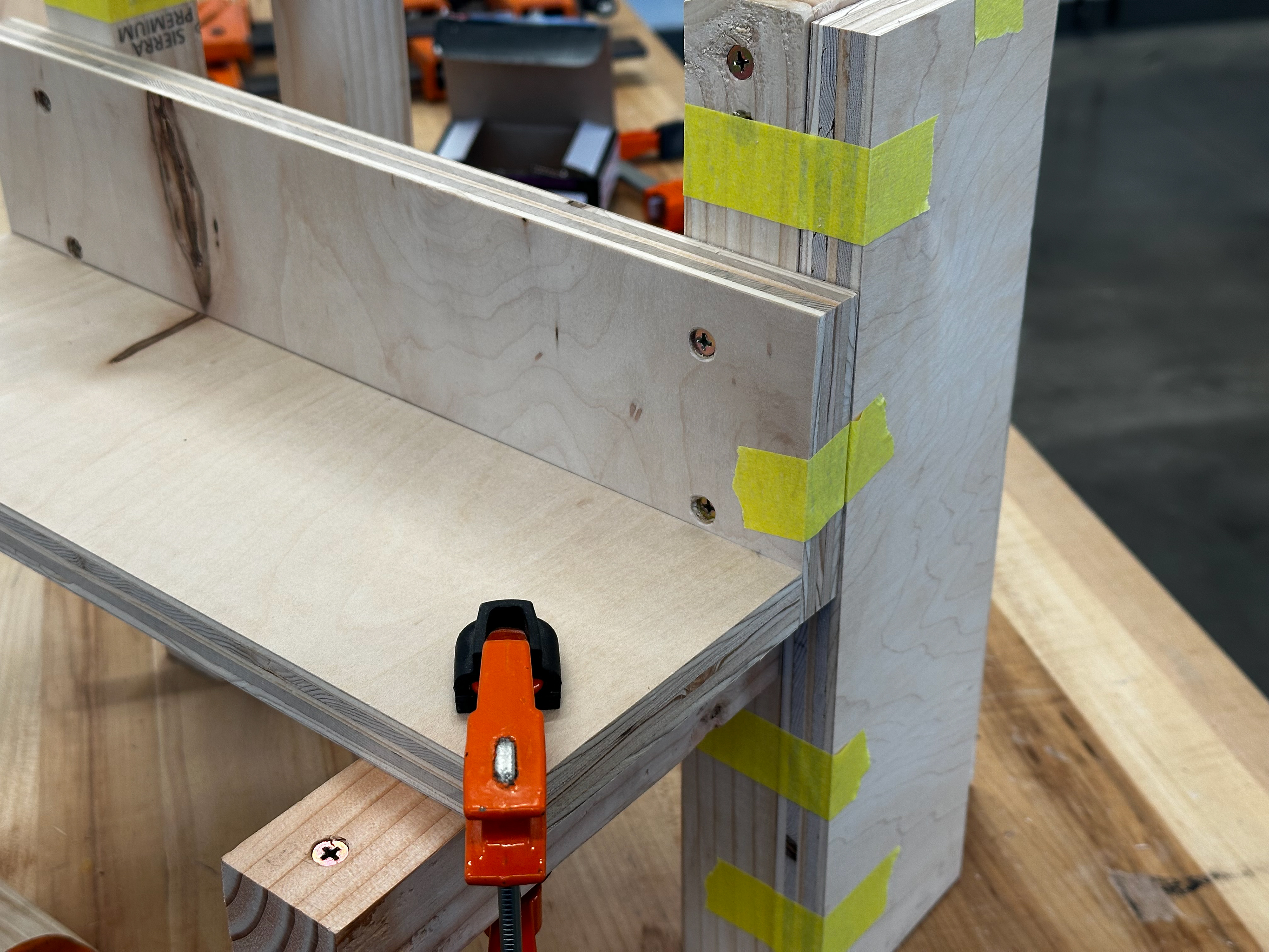
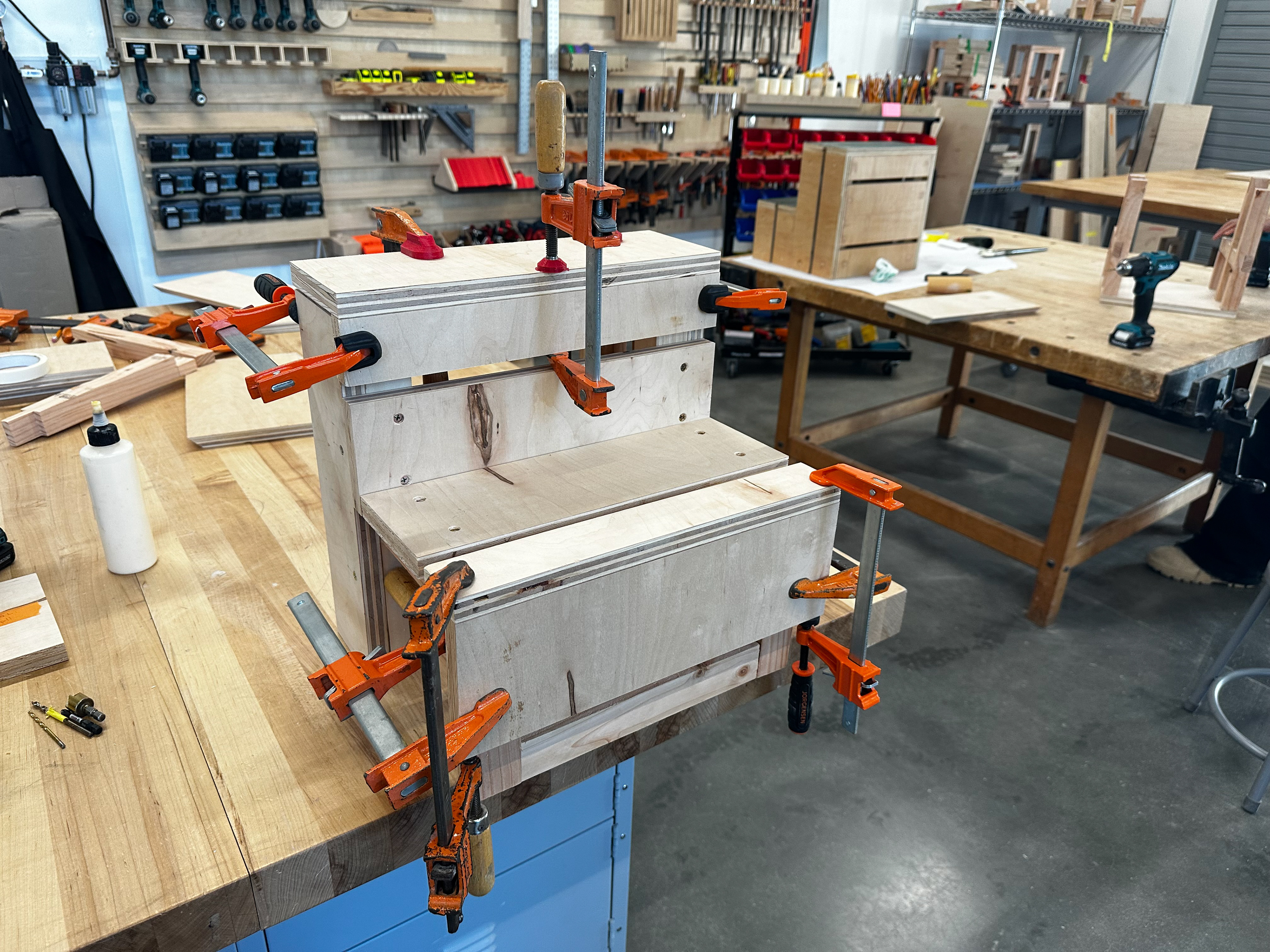
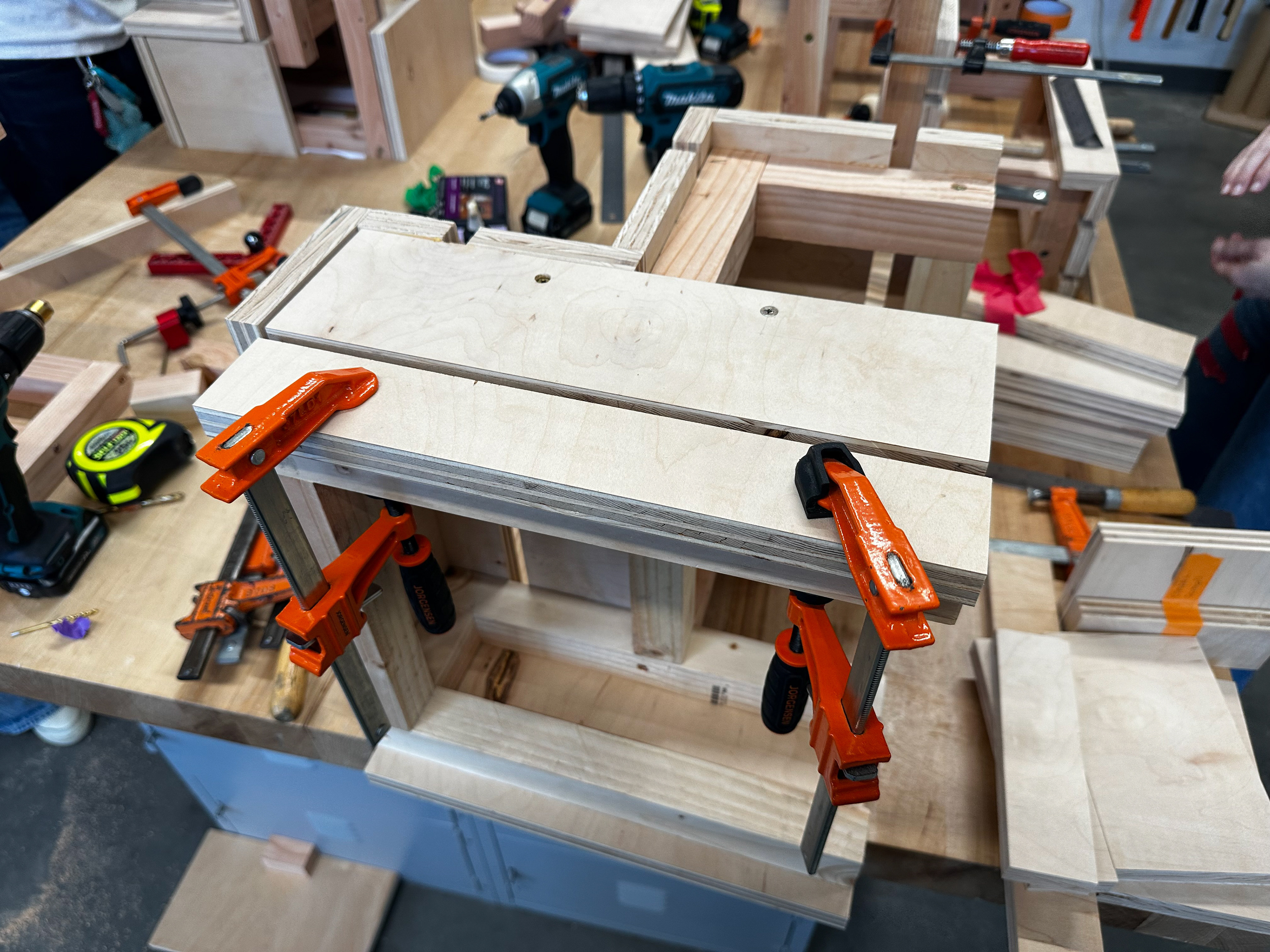
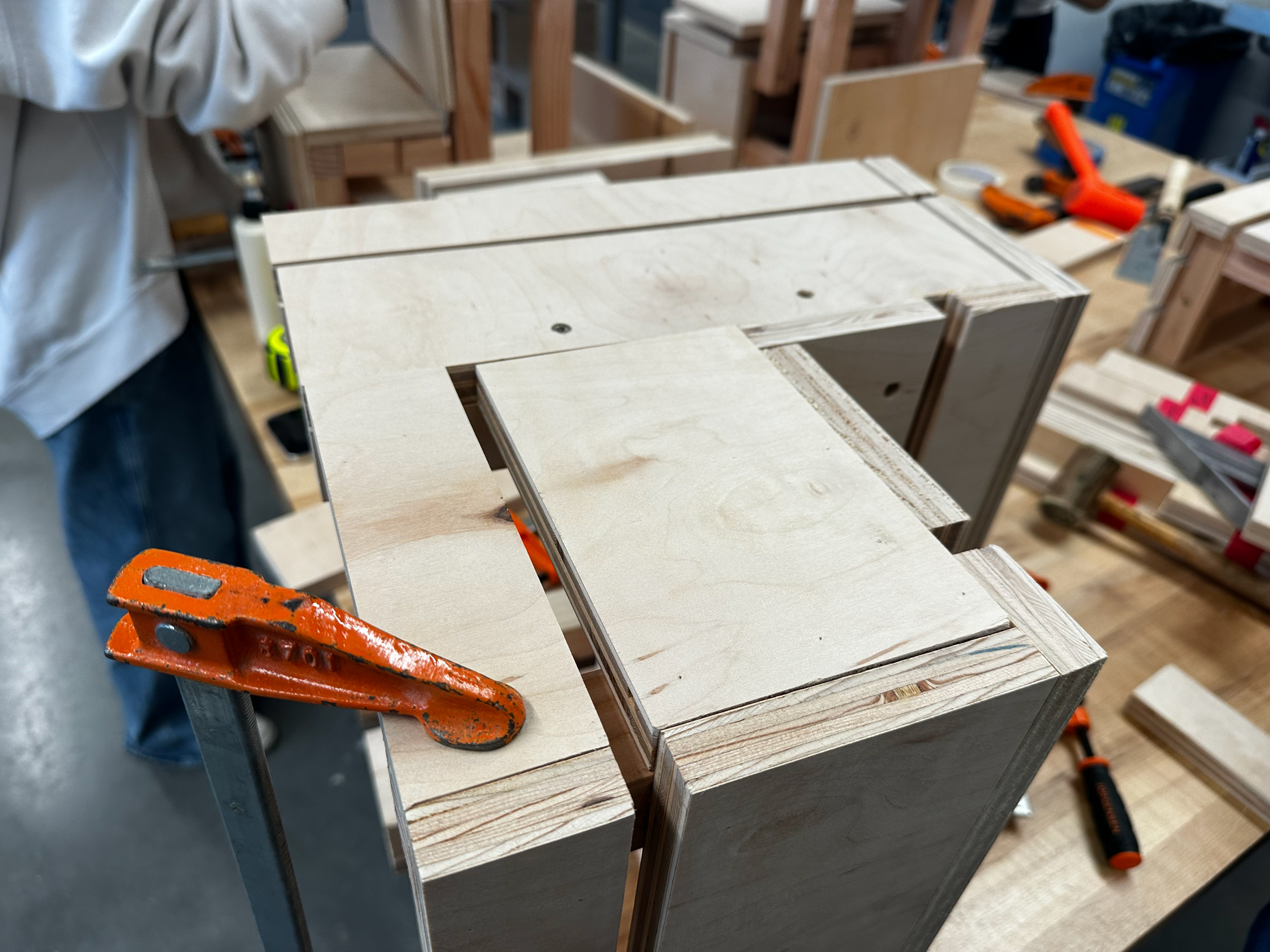
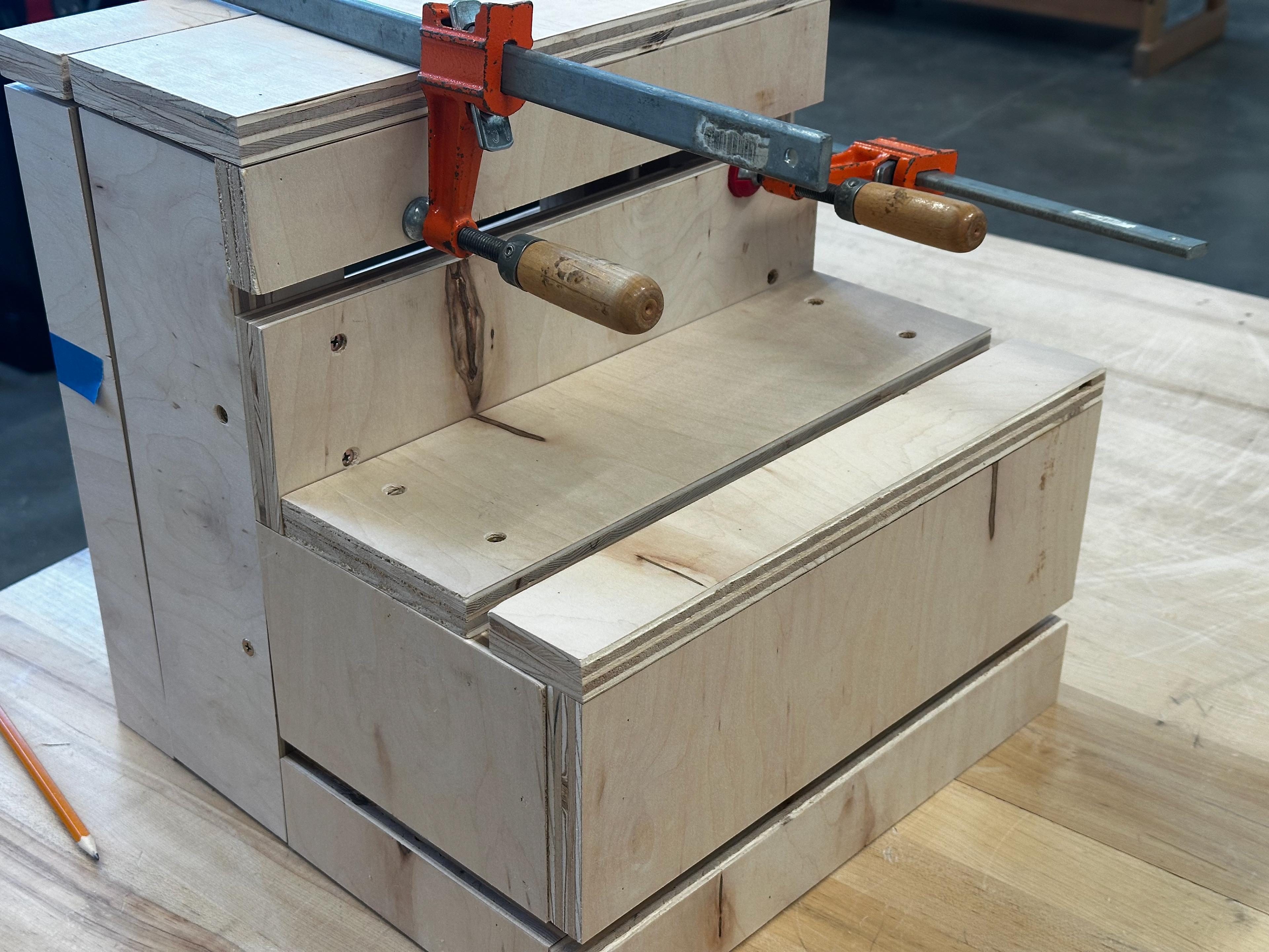
ASSEMBLY PROCESS (Above): A series of images documenting the step stool assembly from the initial structural frame through the final surface preparation. The process begins with assembling and securing the structural framing, followed by attaching the first plywood panels to establish the stool’s form. The remaining front-facing panels are then added, followed by the side panels to complete the exterior skin. The final stage shows the completed stool being sanded to smooth the plywood surfaces, clean the edges, and prepare the piece for its final finish.
REFLECTION
In hindsight, the structural frame could be optimized by incorporating additional framing members to increase rigidity and provide more secure attachment points for the plywood skin. While the existing frame successfully established the overall form of the step stool, additional support would reduce flex and improve its stability. During assembly, I also found that using a larger drill bit for the secondary pilot hole would allow the screws to seat more smoothly, reducing the potential for wood splitting and creating stronger connections. More intentional screw placement could further improve the panel attachment while reducing the reliance on nails and creating a cleaner overall finish.
The fabrication process also highlighted the importance of developing an accurate cut plan and working progressively during assembly. Measuring and cutting the lumber and plywood in stages allowed me to verify dimensions as the stool developed and minimize material waste. For a future iteration, I would explore introducing a more visible and complex joinery detail that could function both structurally and aesthetically. This would create an opportunity to showcase the craftsmanship of the frame while making the connection between the structural system and plywood skin a more intentional part of the design.
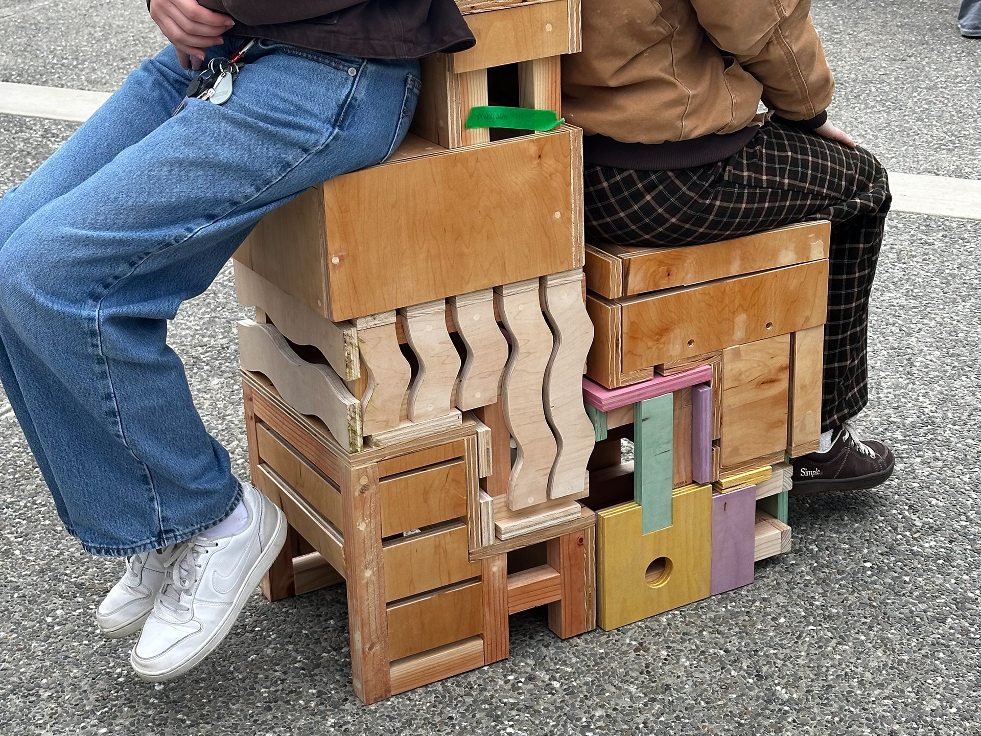
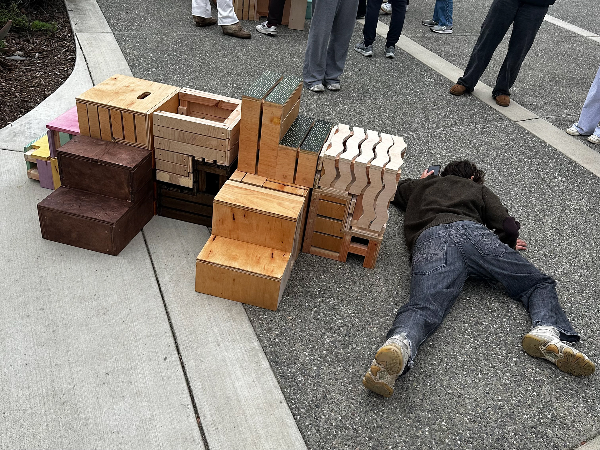
FINAL PROTOTYPE + COLLECTIVE ASSEMBLY (Above): Demonstrating the completed step stool integrated into larger, collective structures alongside the step stools produced by the class. The images illustrate how each prototype contributed to a larger modular system, reinforcing the project’s exploration of the relationship between individual design and collective functionality.